Document Outline
- Introduction
- Scope and Application
- Summary of Method
- Definitions
- Contamination and Interferences
- Safety
- Equipment and Supplies
- Reagents and Standards
- Sample Collection, Preservation, and Storage
- Quality Control
- Calibration and Standardization
- Procedure
- Data Analysis and Calculations
- Method Performance
- Pollution Prevention
- Waste Management
- References
- Tables and Diagrams
- Glossary
- Appendix A
Method 1630
Methyl Mercury in Water by Distillation, Aqueous Ethylation, Purge and Trap, and Cold Vapor Atomic Fluorescence Spectrometry
August, 1998
U.S. Environmental Protection Agency
Office of Water
Office of Science and Technology
Engineering and Analysis Division (4303)
401 M Street SW
Washington, D.C. 20460
Acknowledgments
This method was prepared under the direction of William A. Telliard of the Engineering and Analysis
Division (EAD) within the U.S. Environmental Agency's (EPA's) Office of Science and Technology (OST).
The method was prepared by Nicholas Bloom of Frontier Geosciences under EPA Contract 68-C3-0337
with the DynCorp Environmental Programs Division. Additional assistance in preparing the method was
provided by DynCorp Environmental and Interface, Inc.
Disclaimer
This draft method has been reviewed and approved for publication by the Analytical Methods Staff within
the Engineering and Analysis Division of the U.S. Environmental Protection Agency. Mention of trade
names or commercial products does not constitute endorsement or recommendation for use. EPA plans
further validation of this draft method. The method may be revised following validation to reflect results of
the study.
EPA welcomes suggestions for improvement of this method. Suggestions and questions concerning this
method or its application should be addressed to:
W.A. Telliard
Engineering and Analysis Division (4303)
U.S. Environmental Protection Agency
401 M Street SW
Washington, D.C. 20460
Phone: 202/260-7134
Fax: 202/260-7185
Introduction
This analytical method supports water quality monitoring programs authorized under the Clean Water Act (CWA, the "Act"). CWA Section 304(a) requires EPA to publish water quality criteria that reflect the latest scientific knowledge
concerning the physical fate (e.g., concentration and dispersal) of pollutants, the effects of pollutants on ecological and
human health, and the effect of pollutants on biological community diversity, productivity, and stability.
CWA Section 303 requires each state to set a water quality standard for each body of water within its boundaries. A
state water quality standard consists of a designated use or uses of a water body or a segment of a water body, the water
quality criteria that are necessary to protect the designated use or uses, and an antidegradation policy. These water
quality standards serve two purposes: (1) they establish the water quality goals for a specific water body, and (2) they
are the basis for establishing water quality-based treatment controls and strategies beyond the technology-based controls
required by CWA Sections 301(b) and 306.
In defining water quality standards, the state may use narrative criteria, numeric criteria, or both. However, the 1987
amendments to CWA required states to adopt numeric criteria for toxic pollutants (designated in Section 307(a) of the
Act) based on EPA Section 304(a) criteria or other scientific data, when the discharge or presence of those toxic
pollutants could reasonably be expected to interfere with designated uses.
In some cases, these water quality criteria are as much as 280 times lower than those achievable using existing EPA
methods and required to support technology-based permits. Therefore, EPA developed new sampling and analysis
methods to specifically address state needs for measuring toxic metals at water quality criteria levels, when such
measurements are necessary to protect designated uses in state water quality standards. The latest criteria published
by EPA are those listed in the National Toxics Rule (58 FR 60848) and the Stay of Federal Water Quality Criteria for
Metals (60 FR 22228). These rules include water quality criteria for 13 metals, and it is these criteria on which the
new sampling and analysis methods are based. Method 1630 was specifically developed to provide reliable
measurements of methyl mercury at EPA WQC levels.
In developing methods for determination of trace metals, EPA found that one of the greatest difficulties was precluding
sample contamination during collection, transport, and analysis. The degree of difficulty, however, is highly dependent
on the metal and site-specific conditions. This method is designed to preclude contamination in nearly all situations.
It also contains procedures necessary to produce reliable results at the lowest ambient water quality criteria published
by EPA. In recognition of the variety of situations to which this method may be applied, and in recognition of
continuing technological advances, Method 1630 is performance based. Alternative procedures may be used so long
as those procedures are demonstrated to yield reliable results.
Requests for additional copies of this method should be directed to:
U.S. EPA NCEPI
11209 Kenwood Road
Cincinnati, OH 45242
513/489-8190
Method 1630
Note: This method is performance based. The laboratory is permitted to omit any step or modify any
procedure provided that all performance requirements in this method are met. The laboratory may not
omit any quality control analyses. The terms “shall,” “must,” and “may not” define procedures required
for producing reliable data at water quality criteria levels. The terms “should” and “may” indicate
optional steps that may be modified or omitted if the laboratory can demonstrate that the modified
method produces results equivalent or superior to results produced by this method.
1.0 Scope and Application
1.1 This method is for determination of methyl mercury (CH3Hg3) in filtered and unfiltered water by
distillation, aqueous ethylation, purge and trap, desorption, and cold vapor atomic fluorescence
spectrometry (CVAFS). This method is for use in EPA's data gathering and monitoring programs
associated with the Clean Water Act, the Resource Conservation and Recovery Act, the
Comprehensive Environmental Response, Compensation and Liability Act, and the Safe Drinking
Water Act. The method is based on a contractor-developed method (Reference 1) and on
peer-reviewed, published procedures for the determination of CH3Hg in aqueous samples, ranging
from sea water to sewage effluent (References 2-7).
1.2 This method is accompanied by Method 1669: Sampling Ambient Water for Determination of
Trace Metals at EPA Water Quality Criteria Levels (Sampling Method). The Sampling Method is
necessary to preclude contamination during the sampling process.
1.3 This method is designed for determination of CH3Hg3 in the range of 0.02-5 ng/L and may be
extended to higher levels by selection of a smaller sample size.
1.4 The ease of contaminating ambient water samples with the metal(s) of interest and interfering
substances cannot be overemphasized. This method includes suggestions for improvements in
facilities and analytical techniques that should maximize the ability of the laboratory to make
reliable trace metal determinations and minimize contamination (Section 4.0).
1.5 The detection limit and minimum level of quantitation in this method are usually dependent on the
level of background elements rather than instrumental limitations. The method detection limit
(MDL; 40 CFR 136, Appendix B) for CH3Hg has been determined to be 0.02 ng/L when no
background elements or interferences are present. The minimum level (ML) has been established
as 0.06 ng/L. An MDL as low as 0.009 ng/L can be achieved for low CH3Hg samples by using
extra caution in sample handling and reagent selection, particularly the use of "for ultra-low level
only" distillation equipment.
1.6 Clean and ultraclean-The terms "clean" and "ultraclean" have been applied to the techniques
needed to reduce or eliminate contamination in trace metal determinations. These terms are not
used in this method because they lack an exact definition. However, the information provided in
this method is consistent with the summary guidance on clean and ultraclean techniques.
1.7 This method follows the EPA Environmental Methods Management Council's "Format for Method
Documentation."
1.8 This method is "performance based." The analyst is permitted to modify the method to overcome
interferences or lower the cost of measurements if all performance criteria are met. Section 9.1.2
gives the requirements for establishing method equivalency.
1.9 Any modification of this method, beyond those expressly permitted, shall be considered a major
modification subject to application and approval of alternate test procedures under 40 CFR 136.4
and 136.5.
1.10 This method should be used only by analysts who are experienced in the use of CVAFS techniques
and who are thoroughly trained in the sample handling and instrumental techniques described in
this method. Each analyst who uses this method must demonstrate the ability to generate
acceptable results using the procedure in Section 9.2.
1.11 This method is accompanied by a data verification and validation guidance document, Guidance on
the Documentation and Evaluation of Trace Metals Data Collected for CWA Compliance
Monitoring. Data users should state data quality objectives (DQOs) required for a project before
this method is used.
2.0 Summary of Method
2.1 A 100-2000 mL sample is collected directly into specially cleaned, pretested, fluoropolymer or
borosilicate bottle(s) using sample handling techniques specially designed for collection of metals
at trace levels (Reference 6).
2.2 For dissolved CH3Hg, samples are filtered through a 0.45-µm capsule filter.
2.3 Fresh water samples are preserved by adding 4 mL/L of pretested 11.6 M HCl, while saline
samples ([Cl-] > 500 ppm) are preserved with 2 mL/L of 9 M H2SO4solution, to avoid distillation
interferences caused by excess chloride.
2.4 Prior to analysis, a 45-mL sample aliquot is placed in a specially designed fluoropolymer
distillation vessel, and 35 mL of the water is distilled into the receiving vessel at 125°C under N2 flow.
2.5 After distillation, the sample is adjusted to pH 4.9 with an acetate buffer and ethylated in a closed
purge vessel by the addition of sodium tetraethyl borate (NaBEt ).
2.6 The ethyl analog of CH3Hg, methylethyl mercury (CH3CH3CH2Hg), is separated from solution by
purging with N2 onto a graphitic carbon (Carbotrap®) trap.
2.7 The trapped methylethyl mercury is thermally desorbed from the Carbotrap® trap into an inert gas
stream that carries the released methylethyl mercury first through a pyrolytic decomposition
column, which converts organo mercury forms to elemental mercury (Hg0), and then into the cell of
a cold-vapor atomic fluorescence spectrometer (CVAFS) for detection.
2.8 Quality is ensured through calibration and testing of the distillation, ethylation, purging, and
detection systems.
3.0 Definitions
3.1 Apparatus: Throughout this method, the sample containers, sampling devices, instrumentation,
and all other materials and devices used in sample collection, sample processing, and sample
analysis that come in contact with the sample and therefore require careful cleaning will be referred
to collectively as the Apparatus.
3.2 Dissolved methyl mercury: All distillable CH3Hg forms and species found in the filtrate of an
aqueous solution that has been filtered through a 0.45 micron filter.
3.3 Methyl mercury: All acid-distillable Hg, which, upon reaction with NaBEt4 yields methylethyl
mercury. This includes, but is not limited to, CH3Hg+, strongly organo-complexed CH3Hg
compounds, adsorbed particulate CH3Hg, and CH3Hg bound in microorganisms. In freshly
collected samples, dimethyl mercury ((CH3) Hg) will not be recovered as CH3Hg, but in samples
which have been acidified for several days, most (CH3)2Hg has broken down to CH3Hg. In this
method, CH3Hg and total recoverable CH3Hg are synonymous.
3.4 Definitions of other terms used in this method are given in the glossary at the end of the method.
4.0 Contamination and Interferences
4.1 Preventing ambient water samples from becoming contaminated during the sampling and analysis
process constitutes one of the greatest difficulties encountered in trace metals determinations. Over
the last two decades, marine chemists have come to recognize that much of the historical data on
the concentrations of dissolved trace metals in seawater are erroneously high because the
concentrations reflect contamination from sampling and analysis rather than ambient levels.
Therefore, it is imperative that extreme care be taken to avoid contamination when collecting and
analyzing ambient water samples for trace metals.
4.2 Samples may become contaminated by numerous routes. Potential sources of trace metal
contamination during sampling include: metallic or metal-containing labware (e.g., talc gloves that
contain high levels of zinc), containers, sampling equipment, reagents, and reagent water;
improperly cleaned and stored equipment, labware, and reagents; and atmospheric inputs such as
dirt and dust. Even human contact can be a source of trace metal contamination. For example, it
has been demonstrated that dental work (e.g., mercury amalgam fillings) in the mouths of
laboratory personnel can contaminate samples that are directly exposed to exhalation (Reference
5).
4.3 Contamination control
4.3.1 Philosophy-The philosophy behind contamination control is to ensure that any object or
substance that contacts the sample is metal free and free from any material that may
contain Hg or CH3Hg.
4.3.1.1 The integrity of the results produced cannot be compromised by
contamination of samples. This method and the Sampling Method give
requirements and suggestions for control of sample contamination.
4.3.1.2 Substances in a sample cannot be allowed to contaminate the laboratory
work area or instrumentation used for trace metals measurements. This
method gives requirements and suggestions for protecting the laboratory.
4.3.1.3 Although contamination control is essential, personnel health and safety
remain the highest priority. The Sampling Method and Section 5 of this
method give requirements and suggestions for personnel safety.
4.3.2 Avoid contamination-The best way to control contamination is to completely avoid
exposure of the sample to contamination in the first place. Avoiding exposure means
performing operations in an area known to be free from contamination. Two of the most
important factors in avoiding/reducing sample contamination are (1) an awareness of
potential sources of contamination and (2) strict attention to the work being done.
Therefore, it is imperative that the procedures described in this method be carried out by
well-trained, experienced personnel.
4.3.3 Use a clean environment-The ideal environment for processing samples is a class 100
clean room. If a clean room is not available, all sample preparation should be performed
in a class 100 clean bench or a nonmetal glove box fed by mercury-free and particle-free
air or nitrogen. Digestions should be performed in a nonmetal fume hood situated, ideally
in the clean room.
4.3.4 Minimize exposure-The Apparatus that will contact samples, blanks, or standard
solutions should be opened or exposed only in a clean room, clean bench, or glove box so
that exposure to an uncontrolled atmosphere is minimized. When not in use, the
Apparatus should be covered with clean plastic wrap, stored in the clean bench or in a
plastic box or glove box, or bagged in clean zip-type bags. Minimizing the time between
cleaning and use will also minimize contamination.
4.3.5 Clean work surfaces-Before a given batch of samples is processed, all work surfaces in
the hood, clean bench, or glove box in which the samples will be processed should be
cleaned by wiping with a lint-free cloth or wipe soaked with reagent water.
4.3.6 Wear gloves-Sampling personnel must wear clean, non talc gloves during all operations
involving handling of the Apparatus, samples, and blanks. Only clean gloves may touch
the Apparatus. If another object or substance is touched, the glove(s) must be changed
before again handling the Apparatus. If it is even suspected that gloves have become
contaminated, work must be halted, the contaminated gloves removed, and a new pair of
clean gloves put on. Wearing multiple layers of clean gloves will allow the old pair to be
quickly stripped with minimal disruption to the work activity.
4.3.7 Use metal-free Apparatus-All Apparatus used for determination of CH3Hg at ambient
water quality criteria levels must be nonmetallic and free of material that may contain
metals.
4.3.7.1 Construction materials-Only fluoropolymer or borosilicate glass
containers should be used for samples that will be analyzed for Hg
because Hg vapors can diffuse in or out of other materials, resulting in
results that are biased low or high. All materials, regardless of
construction, that will directly or indirectly contact the sample must be
cleaned using the procedures in this method and must be known to be
clean and mercury free before proceeding.
4.3.7.2 Serialization-It is recommended that serial numbers be indelibly marked
or etched on each piece of Apparatus so that contamination can be traced,
and logbooks should be maintained to track the sample from the container
through the labware to introduction into the instrument. It may be useful
to dedicate separate sets of labware to different sample types; e.g.,
receiving waters vs. effluents. However, the Apparatus used for
processing blanks and standards must be mixed with the Apparatus used
to process samples so that contamination of all labware can be detected.
4.3.7.3 The laboratory or cleaning facility is responsible for cleaning the
Apparatus used by the sampling team. If there are any indications that the Apparatus is not clean when received by the sampling team (e.g., ripped
storage bags), an assessment of the likelihood of contamination must be
made. Sampling must not proceed if it is possible that the Apparatus is contaminated. If the Apparatus is contaminated, it must be returned to the
laboratory or cleaning facility for proper cleaning before any sampling
activity resumes.
4.3.8 Avoid sources of contamination-Avoid contamination by being aware of potential
sources and routes of contamination.
4.3.8.1 Contamination by carryover-Contamination may occur when a sample
containing a low concentration of CH3Hg is processed immediately after a
sample containing a relatively high concentration. When an unusually
concentrated sample is encountered, a ethylation blank should be analyzed
immediately following the sample to check for carryover. Samples known
or suspected to contain the lowest concentration of CH3Hg should be
analyzed first followed by samples containing higher levels.
4.3.8.2 Contamination by samples-Significant laboratory or instrument
contamination may result when untreated effluents, in-process waters,
landfill leachates, and other samples containing high concentrations of Hg
or CH3Hg are processed and analyzed. This method is not intended for
application to these samples, and samples containing high concentrations
of trace metals should not be permitted into the clean room and laboratory
dedicated for processing trace metals samples.
4.3.8.3 Contamination by indirect contact-Apparatus that may not directly come
in contact with the samples may still be a source of contamination. For
example, clean tubing placed in a dirty plastic bag may pick up
contamination from the bag and subsequently transfer the contamination
to the sample. Therefore, it is imperative that every piece of the
Apparatus that is directly or indirectly used in the collection, processing,
and analysis of samples be thoroughly cleaned (see Section 6.1.2).
4.3.8.4 Contamination by airborne particulate matter-Airborne particles are less
obvious substances capable of contaminating samples. Samples may be
contaminated by airborne dust, dirt, particles, or vapors from unfiltered
air supplies; nearby corroded or rusted pipes, wires, or other fixtures; or
metal-containing paint. Whenever possible, sample processing and
analysis should occur as far as possible from sources of airborne
contamination.
4.4 Interferences
4.4.1 When the method is properly applied, no significant interferences have been observed in
the analysis of ambient waters.
4.4.2 Distillation of CH3Hg from solution requires a carefully controlled level of HCl in
solution. Distillation will not be quantitative if too little HCl is added, but too much HCl
results in co-distillation of HCl fumes, which interfere with the ethylation procedure.
Therefore fresh water samples must be preserved only with between 0.3% and 0.5% (v/v)
11.6 M HCl, and salt water samples with between 0.1% and 0.2% (v/v) 9 M H2SO4.
4.4.3 Samples preserved with nitric acid (HNO3) cannot be analyzed for CH3Hg as the analyte is
partially decomposed in the distillation step by this reagent.
4.4.4 The fluorescent intensity is strongly dependent upon the presence of molecular species in
the carrier gas that can cause "quenching" of the excited atoms. The Carbotrap® trap
eliminates quenching due to trace gases, but it still remains the analyst's responsibility to
ensure high purity inert carrier gas and a leak-free analytical train. In some rare cases
(such as oil polluted water) low molecular weight organic compounds may purge with the
methylethyl mercury and collect on the Carbotrap® trap, subsequently resulting in signal
quenching during elution. Such cases are best treated by sample dilution prior to
distillation.
4.4.5 Recent investigations have shown that a positive artifact is possible with the distillation
procedure in cases where high inorganic Hg concentrations are present (Reference 7). In
natural waters, approximately 0.01 to 0.05% of the ambient inorganic Hg in solution may
be methylated by ambient organic matter during the distillation step. In most waters,
where the percent CH3Hg is 1-30% of the total, this effect is trivial. However, the analyst
should be aware that in inorganic Hg contaminated waters, the fraction CH3Hg can be <
1% of the total, and so flagging of the data (as representing a maximum estimate of
CH3Hg concentration) may be warranted. In samples with high levels of divalent mercury
(Hg(II)), solvent extraction may be preferable to distillation (Reference 7).
5.0 Safety
5.1 The toxicity or carcinogenicity of each chemical used in this method has not been precisely
determined; however, each compound should be treated as a potential health hazard. Exposure to
these compounds should be reduced to the lowest possible level. It is suggested that the laboratory
perform personal hygiene monitoring of each analyst using this method and that the results of this
monitoring be made available to the analyst.
5.1.1 Chronic Hg exposure may cause kidney damage, muscle tremors, spasms, personality
changes, depression, irritability, and nervousness. Organo-mercurials may cause
permanent brain damage. Because of the toxicological and physical properties of CH3Hg,
pure standards should be handled only by highly trained personnel thoroughly familiar with
handling and cautionary procedures and the associated risks.
5.1.2 It is recommended that the laboratory purchase a dilute standard solution of CH3Hg for
this method. If primary solutions are prepared, they shall be prepared in a hood, and a
NIOSH/MESA-approved toxic gas respirator shall be worn when high concentrations are
handled.
5.2 This method does not address all safety issues associated with its use. The laboratory is
responsible for maintaining a current awareness file of OSHA regulations for the safe handling of
the chemicals specified in this method. A reference file of material safety data sheets (MSDSs)
should also be made available to all personnel involved in these analyses. Additional information
on laboratory safety can be found in References 7-10. The references and bibliography at the end
of Reference 10 are particularly comprehensive in dealing with the general subject of laboratory
safety.
5.3 Samples suspected of containing high concentrations of CH3Hg are handled using essentially the
same techniques employed in handling radioactive or infectious materials. Well-ventilated,
controlled access laboratories are required. Assistance in evaluating the health hazards of
particular laboratory conditions may be obtained from certain consulting laboratories and from
State Departments of Health or Labor, many of which have an industrial health service. Each
laboratory must develop a strict safety program for handling CH3Hg.
5.3.1 Facility-When samples known or suspected to contain high concentrations of CH Hg are
handled, all operations (including removal of samples from sample containers, weighing,
transferring, and mixing) should be performed in a glove box demonstrated to be leakproof
or in a fume hood demonstrated to have adequate airflow. Gross losses to the laboratory
ventilation system must not be allowed. Handling of the dilute solutions normally used in
analytical and animal work presents no inhalation hazard except in an accident.
5.3.2 Protective equipment-Disposable plastic gloves, apron or lab coat, safety glasses or
mask, and a glove box or fume hood adequate for radioactive work should be used.
During analytical operations that may give rise to aerosols or dusts, personnel should wear
respirators equipped with activated carbon filters.
5.3.3 Training-Workers must be trained in the proper method of removing contaminated gloves
and clothing without contacting the exterior surfaces.
5.3.4 Personal hygiene-Hands and forearms should be washed thoroughly after each
manipulation and before breaks (coffee, lunch, and shift).
5.3.5 Confinement-Isolated work areas posted with signs, segregated glassware and tools, and
plastic absorbent paper on bench tops will aid in confining contamination.
5.3.6 Effluent vapors-The effluent from the CVAFS should pass through either a column of
activated charcoal or a trap containing gold or sulfur to amalgamate or react with Hg
vapors.
5.3.7 Waste handling-Good technique includes minimizing contaminated waste. Plastic bag
liners should be used in waste cans. Janitors and other personnel must be trained in the
safe handling of waste.
5.3.8 Decontamination
5.3.8.1 Decontamination of personnel-Use any mild soap with plenty of
scrubbing action.
5.3.8.2 Glassware, tools, and surfaces-Activated carbon powder will adsorb
CH3Hg, eliminating the possible volatilization of CH3Hg. Satisfactory
cleaning may be accomplished by dusting a surface lightly with activated
carbon powder, then washing with any detergent and water.
5.3.9 Laundry-Clothing known to be contaminated should be collected in plastic bags. Persons
who convey the bags and launder the clothing should be advised of the hazard and trained
in proper handling. If the launderer knows of the potential problem, the clothing may be
put into a washer without contact. The washer should be run through a cycle before being
used again for other clothing.
5.3.10 Wipe tests-A useful method of determining cleanliness of work surfaces and
tools is to wipe the surface with a piece of filter paper. Extraction and analysis by
this method can achieve a limit of detection of less than 1 ng per wipe. Less than
0.1 µg per wipe indicates acceptable cleanliness; anything higher warrants further
cleaning. More than 10 µg on a wipe constitutes an acute hazard, requires prompt
cleaning before further use of the equipment or work space, and indicates that
unacceptable work practices have been employed.
6.0 Equipment and Supplies
NOTE: The mention of trade names or commercial products in this method is for illustrative
purposes only and does not constitute endorsement or recommendation for use by the
Environmental Protection Agency. Equivalent performance may be achievable using apparatus,
materials, or cleaning procedures other than those suggested here. The laboratory is
responsible for demonstrating equivalent performance.
6.1 Sampling equipment
6.1.1 Sample collection bottles-fluoropolymer or borosilicate glass, 125- to 1000-mL, with
fluoropolymer or fluoropolymer-lined cap.
6.1.2 Cleaning
6.1.2.1 New bottles are cleaned by heating to 65-75°C in 4 N HCl for at least 48
h. The bottles are cooled, rinsed three times with reagent water, and filled
with reagent water containing 1% HCl. These bottles are capped and
placed in a clean oven at 60-70°C overnight. After cooling, they are
rinsed three more times with reagent water, filled with reagent water
containing 0.4% (v/v) HCl, capped, and placed in a mercury-free class
100 clean bench until the outside of the bottle is dry. The caps are then
tightened with a wrench and the bottles are double-bagged in new
polyethylene zip-type bags. The capped bottles are stored in wooden or
plastic boxes until use.
6.1.2.2 To avoid long-term accumulation of Hg or CH3Hg on the bottle walls due
to trace organic coatings, used bottles are filled with reagent water
containing 0.02 N BrCl solution and allowed to stand over night. The
BrCl is neutralized with the addition of 0.2 mL of 20% NH2OH solution.
The bottles are then cleaned exactly as in Section 6.1.2.1, except that they
soak only 6-12 h in hot 4 N HCl.
6.1.2.3 Bottle blanks should be analyzed as described in Section 9.4.4.1 to verify
the effectiveness of the cleaning procedures.
6.1.3 Filtration Apparatus
6.1.3.1 Filter-0.45-µm, 15-mm diameter capsule filter (Gelman Supor 12175, or
equivalent)
6.1.3.2 Peristaltic pump-115-V a.c., 12-V d.c., internal battery, variable-speed,
single-head (Cole-Parmer, portable, "Masterflex L/S," Catalog No. H-
07570-10 drive with Quick Load pump head, Catalog No. H-07021-24,
or equivalent).
6.1.3.3 Tubing-styrene/ethylene/butylene/silicone (SEBS) resin for use with
peristaltic pump, approx 3/8-in i.d. by approximately 3 ft (Cole-Parmer
size 18, Catalog No. G-06464-18, or approximately 1/4-in i.d., Cole-
Parmer size 17, Catalog No. G-06464-17, or equivalent). Tubing is
cleaned by soaking in 5-10% HCl solution for 8-24 h. It is rinsed with
reagent water on a clean bench in a clean room and dried on the clean
bench by purging with metal-free air or nitrogen. After drying, the tubing
is double-bagged in clear polyethylene bags, serialized with a unique
number, and stored until use.
6.2 Equipment for bottle and glassware cleaning
6.2.1 Vat, 100-200 L, high-density polyethylene (HDPE), half filled with 4 N HCl in reagent
water.
6.2.2 Panel immersion heater, 500-W, all-fluoropolymer coated, 120 vac (Cole-Parmer H-
03053-04, or equivalent)
NOTE: Read instructions carefully!! The heater will maintain steady state, without
temperature feedback control, of 60-75°C in a vat of the size described. However, the
equilibrium temperature will be higher (up to boiling) in a smaller vat. Also, the heater plate
MUST be maintained in a vertical position, completely submerged and away from the vat walls
to avoid melting the vat or burning out!
6.2.3 Laboratory sink in class 100 clean area, with high-flow reagent water (Section 7.1) for
rinsing.
6.2.4 Clean bench, class 100, for drying rinsed bottles.
6.2.5 Oven, stainless steel, in class 100 clean area, capable of maintaining ± 5°C in the 60-70°C
temperature range.
6.3 Cold vapor atomic fluorescence spectrometer (CVAFS): The CVAFS system used may either be
purchased from a supplier, or built in the laboratory from commercially available components.
6.3.1 Commercially available: Tekran Model 2357 CVAFS, Brooks-Rand Model III CVAFS,
or equivalent
6.3.2 Custom-built CVAFS (Reference 11). Figure 1 shows the schematic diagram. The system
consists of the following:
6.3.2.1 Low-pressure 4-W mercury vapor lamp
6.3.2.2 Far UV quartz flow-through fluorescence cell-12 mm x 12 mm x 45
mm, with a 10-mm path length (NSG Cells, or equivalent).
6.3.2.3 UV-visible photomultiplier (PMT)-sensitive to < 230 nm. This PMT is
isolated from outside light with a 253.7-nm interference filter (Oriel
Corp., or equivalent).
6.3.2.4 Photometer and PMT power supply (Oriel Corp., or equivalent), to
convert PMT output (nanoamp) to millivolts
6.3.2.5 Black anodized aluminum optical block-holds fluorescence cell, PMT,
and light source at perpendicular angles, and provides collimation of
incident and fluorescent beams (Frontier Geosciences Inc., or equivalent).
6.3.2.6 Flowmeter, with needle valve capable of keeping the carrier gas at a
reproducible flow rate of 30 mL/min
6.3.2.7 Ultra high-purity argon (grade 5.0)
6.4 Equipment for CH3Hg purging system-Figure 2a shows the schematic diagram for the purging
system. The system consists of the following:
6.4.1 Flow meter/needle valve-capable of controlling and measuring gas flow rate to the purge
vessel at 350 (± 50) mL/min.
6.4.2 Fluoropolymer fittings-connections between components and columns are made using
6.4-mm o.d. fluoropolymer tubing and fluoropolymer friction-fit or threaded tubing
connectors. Connections between components requiring mobility are made with 3.2-mm
o.d. fluoropolymer tubing because of its greater flexibility.
6.4.3 Cold vapor generator (bubbler)-200-mL borosilicate glass (15 cm high x 5.0 cm
diameter) with standard taper 24/40 neck, fitted with a sparging stopper having a coarse glass frit that extends to within 0.2 cm of the bubbler bottom (Frontier Geosciences, Inc.,
or equivalent).
6.5 Equipment for the isothermal gas chromatography (GC) system.
6.5.1 Figure 1 shows the schematic for the interface of the GC with the CVAFS detector
(Reference 6).
6.5.2 Figure 2b shows the orientation consideration for purging and desorbing CH3Hg from the
Carbotrap® traps.
6.5.3 Carbotrap® traps-10-cm x 6.5-mm o.d. x 4-mm i.d. quartz tubing. The tube is filled with
3.4 cm of 30/45 mesh Carbotrap® graphitic carbon adsorbant (Supelco, Inc., or
equivalent). The ends are plugged with silanized glass wool.
6.5.3.1 Traps are fitted with 6.5-mm i.d. fluoropolymer friction-fit sleeves for
making connection to the system. When traps are not in use,
fluoropolymer end plugs are inserted in trap ends to eliminate
contamination.
6.5.3.2 At least six traps are needed for efficient operation.
6.5.3.3 Because the direction of flow is important in this analysis, the crimped end
of the Carbotrap® trap will be referred to as "side A," while the
uncrimped end will be referred to as "side B."
6.5.4 Heating of Carbotrap® traps-To desorb CH3Hg collected on a trap, heat for 45 sec to
450-500°C (a barely visible red glow when the room is darkened) with a coil consisting of
75 cm of 24-gauge Nichrome wire at a potential of 16-20 vac. Potential is applied and
finely adjusted with an autotransformer.
6.5.5 Timer-The heating interval is controlled by a timer-activated 120-V outlet, into which the
heating coil autotransformer is plugged.
6.5.6 Isothermal GC-Consists of two parts, a custom fabricated packed GC column, and a
custom fabricated constant temperature oven.
6.5.6.1 The column is 1 m long, made from 0.25 inch OD by 4 mm ID
borosilicate glass GC column tubing. The column is formed into an 8 cm
diameter coil, with 15 cm straight extensions from each end. The column
is silanized, packed in the coiled portion with 60/80 mesh 15% OV-3 on
acid-washed Chromasorb W, and then conditioned under inert gas flow at
200°C. A column meeting these specifications may be custom fabricated
(Supelco Inc., or equivalent).
6.5.6.2 The GC oven consists of a 500-watt aluminum jacketed heating mantle,
fitted with a custom machined fluoropolymer lid (14 cm OD by 1 cm
thick). The lid is attached with stainless steel screws and contains three
threaded holes (0.25 inch female NPT) in a triangular pattern in the top.
The spacing of the holes conforms exactly to the spacing between the two
15 cm glass extensions of the GC column.
6.5.6.3 Fluoropolymer fittings, with 0.25-inch male NPT threads on the bottom
and 0.25-inch compression fittings on top, are placed into the threaded
holes. The GC column is secured into the oven by passing the glass
extensions through two of the fluoropolymer fittings, so that 3 cm of the
glass extensions protrude from the top, and tightening the compression
fittings. The fluoropolymer lid holding the GC column is then screwed to
the top of the oven.
6.5.6.4 Temperature feedback control (110 ± 2°C) is achieved through a
thermocouple temperature controller. The oven is plugged into the
controller and the thermocouple probe is inserted through the third
fluoropolymer fitting in the lid, such that the sensor is located near the
center of the GC coil.
6.5.6.5 Several research groups have successfully interfaced the
Carbotrap®/CVAFS system directly to a commercial gas chromatograph.
The use of capillary column GC will result in better peak separation,
although at higher cost.
6.5.7 Pyrolytic column-The output from the GC oven is connected directly to a high
temperature column to decompose eluted organo-mercurial compounds to Hg0. The output
of the pyrolytic column is connected to the inlet of the CVAFS system.
6.5.7.1 The column consists of a 20-cm length of quartz tubing, packed over the
central 10 cm with quartz wool.
6.5.7.2 The column is heated to orange heat (~ 700°C) by a 1 m length of 22
gauge Nichrome wire, tightly wrapped around the quartz wool packed
portion of the tube. The temperature of the coil is adjusted by visual
inspection of the color, using a 0-120 volt autotransformer.
6.6 Recorder-Any multi-range millivolt chart recorder or integrator with a range compatible with the
CVAFS is acceptable. By using a two pen recorder with pen sensitivity offset by a factor of 10,
the dynamic range of the system is extended to 103.
6.7 Distillation unit-The distillation unit is a custom made temperature controlled aluminum block
heater, as shown schematically in Figure 3 (Frontier Geosciences Inc., or equivalent).
6.7.1 Heating block insulation-Each heating block is encased first in refractory spun rock
insulation (1 inch thickness) and then an exterior wood shell for rigidity.
6.7.2 Each heating block (10 cm wide x 20 cm long x 15 cm high) is bored with five 31 mm
diameter holes (evenly spaced), 120 mm deep. A 3/8 inch diameter hole is bored to 90%
of the block length, perpendicular to and behind the distillation tube holes, to accommodate
a cylindrical heating element. A 2 mm diameter hole is bored parallel to the heating
element hole, and 2 cm above it, to accommodate the temperature sensor.
6.7.3 Heating element-Each heating block is equipped with a 750 watt cylindrical heating
element, 6 inches long by 3/8 inch diameter (Omega Inc.), immobilized in its respective
hole by a dab of silicone glue.
6.7.4 Type J thermocouple probe-Each heating block is equipped with a type J thermocouple
probe immobilized in its respective hole by a dab of silicone glue.
6.7.5 Digital temperature controller-The heating element and thermocouple are connected to a
digital temperature controller.
6.7.6 Fluoropolymer vials with caps-The distillation unit is designed to accommodate 60-mL
fluoropolymer vials (part number 0202, Savillex, or equivalent). The original caps are
used to close the vials when distillate is to be stored until analysis.
6.7.6.1 For each distillation, two identical vials are needed: a distillation vessel
and a receiving vessel. For convenience, each vial should be engraved
with a line at 40.0 mL (obtained by weighing 40 g of water in the vial),
and a unique identification number, both on the vial and the cap.
6.7.6.2 Fluoropolymer vials are acid cleaned initially as described for other
fluoropolymer ware and stored filled with 0.5% HCl. After use, receiving
vials are rinsed with reagent water and filled with 0.5% HCL. The tubing
is looped around the cap as described in Section 6.7.7.1, and the vials are
placed in a 70°C (± 5°C) oven overnight. Cleaning is the same for the
distillation vials, with the exception that first the vials, caps, and tubing are thoroughly scrubbed with an alkaline detergent and test tube brush to
remove any residues from the samples.
6.7.7 Purge caps-The standard caps on the fluoropolymer vials are replaced with purge caps
(part number 33-2-2, Savillex, or equivalent) for distillation purposes.
6.7.7.1 Fluoropolymer tubing-each purge cap is threaded with a piece of 1/8
inch fluoropolymer tubing, approximately 30-40 cm long. One end is
pulled through one of the holes in the cap, down to a length that will allow
it to reach the bottom of the distillation vial when the vial is screwed onto
the cap. The bottom end of this tubing is cut at a 45° angle. The outside
end of the tubing is cut perpendicularly and is looped around and inserted
into the second cap hole when not in use (to keep the system closed and
clean).
6.7.8 Aluminum distillation cover-The cover for the heating block consists of a 5 cm high
aluminum block of the same cross section as the heating block (10 cm wide x 20 cm long),
which has been milled out completely except for a 0.5 cm shell all around. In this lid is
placed a series of 5 slots, 0.5 cm wide by 3 cm high, on each of the long sides, to allow
passage of the distillation tubing in and out of the distillation vessels.
NOTE: It is very important that the heating block have an aluminum top covering the vessels,
to avoid condensation and refluxing of the sample in the distillation vessels.
6.7.9 Polyethylene container-Distillate is received and cooled in a fluoropolymer receiving vial
supported in an ice bath in a polyethylene container. A box approximately 15 cm wide x
25 cm long x 10 cm high is a convenient container, and holes to accommodate the
receiving vials can be cut into the lid of each box. Suitable boxes are generally available
at sundries stores as storage containers.
6.7.10 Rotometer/needle valve-Five needle valve/rotometer (0-300 mL/min N2)assemblies are required, one for each distillation vessel in the heating block.
These rotometers can be mounted in banks of 5 for each distillation block, with all
rotometers connected to a common gas manifold.
6.7.10.1 Fluoropolymer tubing-Inert gas (N2 or Ar at 0.5-1 atm) is brought from
the regulator to the manifold and from the rotometer outlets to the
distillation vials by 1/8 inch fluoropolymer tubing.
6.7.11 The entire distillation set-up can be mounted on a stepped structure or shelving
unit, such that the banks of rotometers are on the top and easily adjustable. Below the rotometers are the distillation blocks, and lower still, the ice baths for the
receiving vessels.
6.8 Pipettors-All-plastic pneumatic fixed-volume and variable pipettors in the range of 10-uL to 5.0-
mL.
6.9 Analytical balance capable of weighing to the nearest 0.01 g.
7.0 Reagents and Standards
7.1 Reagent water-18-M ohm minimum, ultrapure deionized water starting from a prepurified (distilled,
reverse osmosis, etc.) source. Water should be monitored for Hg, especially after ion exchange
beds are changed.
7.2 Air-It is very important that the laboratory air be low in both particulate and gaseous Hg.
Ideally, Hg work should be conducted in a new laboratory with mercury-free paint on the walls.
Outside air, which is very low in Hg, should be brought directly into the class 100 clean bench air
intake. If this is impossible, air coming into the clean bench can be cleaned for Hg by placing a
gold-coated cloth prefilter over the intake.
7.2.1 Gold-coated cloth filter: Soak 2 m2 of cotton gauze in 500 mL of 2% gold chloride solution
at pH 7. In a hood, add 100 mL of 30% NH2OH·HCl solution, and homogenize into the
cloth with gloved hands. The material will turn black as colloidal gold is precipitated.
Allow the mixture to set for several hours, then rinse with copious amounts of reagent
water. Squeeze-dry the rinsed cloth, and spread flat on newspapers to air-dry. When dry,
fold and place over the intake prefilter of the laminar flow hood.
NOTE: Great care should be taken to avoid contaminating the laboratory with gold dust. This
could cause interferences with the analysis if gold becomes incorporated into the samples or
equipment. The gilding procedure should be done in a remote laboratory if at all possible.
7.3 Hydrochloric acid-Trace-metal purified reagent HCl containing less than 5 pg/mL Hg. CH3Hg is
not stable in concentrated acid, so the acid does not need to be tested for CH3Hg.
7.4 Sulfuric acid-Trace-metal purified reagent H2SO4 containing less than 5 pg/mL Hg. CH3Hg is
not stable in concentrated acid, so the acid does not need to be tested for CH3Hg.
7.5 1% APDC solution-To 100 mL of reagent water, add 1.0 g of reagent grade APDC (ammonium
pyrrolidine dithiocarbamate), and shake to dissolve. The solution is purified by extraction with
three 10 mL aliquots of methylene chloride.
7.6 Glacial acetic acid-Reagent grade
7.7 2 M Acetate buffer-2 moles of reagent grade sodium acetate (272 g) and 2 moles of reagent grade
glacial acetic acid (118 mL) dissolved in reagent water to give a final volume of 1.0 L. To purify
the buffer of traces of CH3Hg, add 0.5 mL of 1% NaBEt4 and purge the solution overnight with
Hg-free N2 or Ar. This solution has an indefinite lifetime when stored in a fluoropolymer bottle at
room temperature.
7.8 1% Sodium tetraethyl borate-This reagent is purchased in 1.0-g air-sealed bottles (Strem
Chemical, or equivalent. One hundred milliliters of 2% KOH in reagent water is prepared in a
fluoropolymer bottle and chilled to 0°C. The bottle of NaBEt4 is rapidly opened and approximately
4
5 mL of the KOH solution poured in. The reagent bottle is capped and shaken to dissolve the
NaBEt4 . This is poured into the 100 mL bottle of KOH solution, and shaken to mix. Immediately,
the 1% NaBEt4 solution in 2% KOH is poured into fifteen (15) 7-mL fluoropolymer bottles, which
are capped and placed in a low temperature freezer. For use, one of these bottles is removed and
thawed until it starts to form a liquid layer. The reagent is then used until just before all of the ice
is melted. Usually this lasts about 3 h if the bottle is placed in the refrigerator between uses.
NOTE: It is imperative that this reagent be exposed to air a minimum length of time. Thus,
when removing reagent, open and close the lid quickly and tightly!
Frozen bottles of NaBEt4 will keep for at least one week. If any doubt arises about the quality of
the ethylating reagent, make a new batch, as the old material often gives good results for reagent
water spikes, but not for environmental samples. Do not use NaBEt4 solid or solutions if they have
a yellow color.
WARNING: NaBEt4 is toxic, gives off toxic gases (triethylboron), and is spontaneously combustible. To discard unused portions of ethylating agent and empty bottles, place into a large
beaker of 1N HCl in the hood. Triethylboron will bubble off to the air where it is eventually
oxidized to harmless boric acid. Leave the acid beaker in the hood indefinitely, or boil down to ½
volume to destroy residues before discarding as any acid waste.
7.9 Methyl mercuric chloride(s)-A 5-g bottle of methyl mercuric chloride (s), reagent grade (Strem
Chemical, or equivalent).
7.10 Stock methyl mercury standard-Either procure certified CH3Hg solution (Frontier Geosciences
Inc., or equivalent) or prepare the stock solutions in the laboratory. Dissolve the contents of an
entire 5-g bottle of methyl mercuric chloride in reagent water containing 0.5% (v/v) glacial acetic
acid and 0.2% (v/v) HCl in a fluoropolymer bottle. This solution contains 4000-5000 mg/L
CH3Hg as Hg. It does not have a specific titre because, due to the contamination danger, the
methyl mercuric chloride is not weighed. The stock solution has an indefinite lifetime when stored in an amber glass bottle with an fluoropolymer lid at room temperature. Do not make or keep this
concentrated stock solution in the trace mercury laboratory.
NOTE: Making a CH3Hg standard rather than purchasing one requires the laboratory to have available the technology to perform analyses with Method 1631: Mercury in Water by Oxidation,
Purge and Trap, and Cold Vapor Atomic Fluorescence Spectrometry. Total Hg and labile Hg
(II) determinations, made with Method 1631, are necessary to accurately determine the CH3Hg concentration of the standards. Additionally, laboratories must be cautioned against assuming
that purchased CH3Hg stock solution will remain constant in concentration. Purchased stocksolution has been seen to degrade occasionally, in one case from 1000 mg/L to 4 mg/L.
7.11 Secondary methyl mercury standard-Dilute 1.00 mL of stock solution (B) to 1000.0 mL with
reagent water containing 0.5% (v/v) glacial acetic acid and 0.2% (v/v) HCl. This solution contains
approximately 4-5 mg/L (5.00 ng/mL) CH3Hg as Hg. The exact CH3Hg titre is determined as
indicated in Sections 7.11.1-7.11.4. The secondary CH3Hg standard solution has been observed to
maintain its titre over a year when stored in a fluoropolymer bottle in the refrigerator.
7.11.1 Dilute the secondary standard 1:10 with concentrated BrCl solution (0.100 mL of
secondary stock solution added to 0.900 mL BrCl in a small FEP vial). Allow the
solution to oxidize for at least 4 h. The total Hg in the dilution may then be
analyzed using dual amalgamation/CVAFS, by comparison to a dilution of NIST-
3133 (as in Method 1631). A mean of at least seven replicate analyses of the
secondary stock solution is necessary to accurately quantify the total Hg
concentration of the solution.
7.11.2 Analyze the secondary standard for labile Hg(II) using Method 1631 by directly
reducing an aliquot of standard solution with SnCl , but without prior BrCl2oxidation as performed in Section 7.11.1. At least two determinations of labile
Hg(II) must be made of the stock solution.
7.11.3 Calculate the CH Hg in the secondary CH3Hg standard solution by subtracting the
mean labile Hg(II) concentration from the mean total Hg concentration.
7.11.4 If the secondary CH3Hg stock solution drops below 98.0% CH3Hg, discard the
solution and make a fresh secondary solution.
7.12 Working methyl mercury standard-Prepare a dilution of the secondary CH3Hg standard using
reagent water containing 0.5% (v/v) glacial acetic acid and 0.2% (v/v) HCl. A convenient
concentration for this standard is 1.00 ng/mL CH3Hg as Hg. This solution will maintain its titre
for more than one month when kept in a fluoropolymer bottle on the lab bench top. Refrigeration
is not necessary.
7.13 IPR and OPR solutions-Using the working CH3Hg standard (Section 7.9), prepare IPR and OPR
solutions at a concentration of 0.5 ng/L as Hg in reagent water.
7.14 Nitrogen-Grade 4.5 (standard laboratory grade) nitrogen that has been further purified by the
removal of Hg using a gold-coated sand trap (Section 7.16).
7.15 Argon-Grade 5.0 (ultra high-purity, GC grade) that has been further purified by the removal of
Hg using a gold-coated sand trap (Section 7.16).
7.16 Gold-coated sand trap-The trap is made from 10-cm x 6.5-mm o.d. x 4-mm i.d. quartz tubing.
The tube is filled with 3.4 cm of gold-coated 45/60 mesh quartz sand (Frontier Geosciences Inc., or
equivalent). The ends are plugged with quartz wool. Traps are fitted with 6.5-mm i.d.
fluoropolymer friction-fit sleeves for connection to the system.
8.0 Sample Collection, Preservation, and Storage
8.1 Before samples are collected, consideration should be given to the type of data required (i.e.,
dissolved or total), so that appropriate preservation and pretreatment steps can be taken. The pH
of all aqueous samples must be tested immediately before removing an aliquot for processing or
direct analysis to ensure the sample has been properly preserved.
NOTE: Do not dip pH paper or pH meter into the sample; remove a small aliquot with a clean
pipet and test the aliquot pH.
8.2 Samples are collected into rigorously cleaned fluoropolymer bottles with fluoropolymer or
fluoropolymer-lined caps. Borosilicate glass bottles may be used if Hg and Hg species are the only
target analytes. It is critical that the bottles have tightly sealing caps to avoid diffusion of
atmospheric Hg through the threads. Polyethylene sample bottles must not be used (Reference 13).
8.3 Collect samples using the Sampling Method (Reference 8). Procedures in the Sampling Method
are based on rigorous protocols for collection of samples for Hg (Reference 13).
NOTE: Discrete samplers have been found to contaminate samples with Hg at the ng/L level;
therefore, great care should be exercised if this type of sampler is used to collect samples. It
may be necessary for the sampling team to use other means of sample collection if samples are
found to be contaminated using the discrete sampler
8.4 Sample filtration-For dissolved CH3Hg, samples and field blanks are filtered through a 0.45-µm
capsule filter (Section 6.1.3.1). The Sampling Method describes filtering procedures.
8.5 Preservation-Samples are preserved by adding 4 mL/L of concentrated HCL (to allow both
CH3Hg and total Hg determination). Saline samples ([Cl-]>500 ppm) are preserved with 2 mL/L
of 9 M H2SO4 solution. Acid-preserved samples are stable for at least six months, if kept dark and
cool.
8.5.1 Samples may be shipped to the laboratory unpreserved if they are (1) collected in
fluoropolymer bottles, (2) filled to the top with no head space, (3) capped tightly, and (4)
maintained at 0-4°C from the time of collection until preservation. The samples must be
acid-preserved within 48 h of sampling.
8.5.2 Handling of the samples in the laboratory should be undertaken on a mercury-free clean
bench, after rinsing the outside of the bottles with reagent water and drying in the clean air
hood.
NOTE: Due to the potential for contamination, it is recommended that filtration and
preservation of samples be performed in the clean room in the laboratory. However, if
circumstances in the field prevent overnight shipment of samples, the samples should be filtered
and preserved in a designated clean area in the field in accordance with the procedures given in
Sections 8.3 and 8.4 of Method 1669.
8.6 Storage-Sample bottles should be stored in clean (new) polyethylene bags until analysis. To
maintain CH3Hg concentrations without degradation, it is necessary to keep acid-preserved
samples dark and cool. If properly preserved, samples can be held up at least six months before
analysis.
9.0 Quality Control
9.1 Each laboratory that uses this method is required to operate a formal quality assurance program
(Reference 14). The minimum requirements of this program consist of an initial demonstration of
laboratory capability, ongoing analysis of standards and blanks as a test of continued performance,
and the analysis of matrix spikes (MS) and matrix spike duplicates (MSD) to assess accuracy and
precision. Laboratory performance is compared to established performance criteria to determine
whether the results of analyses meet the performance characteristics of the method.
9.1.1 The analyst shall make an initial demonstration of the ability to generate acceptable
accuracy and precision with this method. This ability is established as described in
Section 9.2.
9.1.2 In recognition of advances that are occurring in analytical technology, the analyst is
permitted certain options to improve results or lower the cost of measurements. These
options include automation of the system, solvent extraction in place of distillation (Reference 2), direct electronic data acquisition, or changes in the detector (i.e., CVAAS,
AES, ICP/MS). Changes in the principle of the determinative technique, such as the use
of colorimetry, are not allowed. If an analytical technique other than the CVAFS
technique specified in this method is used, that technique must have a specificity for
CH Hg equal to or better than the specificity of the technique in this method.
9.1.2.1 Each time this method is modified, the analyst is required to repeat the
procedure in Section 9.2. If the change will affect the detection limit of
the method, the laboratory is required to demonstrate that the MDL (40
CFR Part 136, Appendix B) is lower than one-third the regulatory
compliance level or lower than the MDL of this method, whichever is
higher. If the change will affect calibration, the analyst must recalibrate
the instrument according to Section 10.
9.1.2.2 The laboratory is required to maintain records of modifications made to
this method. These records include the following, at a minimum:
9.1.2.2.1 The names, titles, addresses, and telephone numbers of the
analyst(s) who performed the analyses and modification, and the
quality control officer who witnessed and will verify the analyses
and modification
9.1.2.2.2 A narrative stating the reason(s) for the modification(s)
9.1.2.2.3 Results from all quality control (QC) tests comparing the
modified method to this method, including the following:
(a)
Calibration (Section 10)
(b)
Initial precision and recovery (Section 9.2)
(c)
Analysis of blanks (Section 9.4)
(d)
Matrix spike/matrix spike duplicate analysis (Section
9.3)
(e)
Ongoing precision and recovery (Section 9.5)
(f)
Quality control sample (Section 9.6)
9.1.2.2.4 Data that will allow an independent reviewer to validate each
determination by tracking the instrument output to the final result.
These data are to include the following:
(a)
Sample numbers and other identifiers
(b)
Processing dates
(c)
Analysis dates
(d)
Analysis sequence/run chronology
(e)
Sample weight or volume
(f)
Copies of logbooks, chart recorder, or other raw data
output
(g)
Calculations linking raw data to the results reported
9.1.3 Analyses of MS and MSD samples are required to demonstrate the accuracy and precision
and to monitor matrix interferences. Section 9.3 describes the procedure and QC criteria
for spiking.
9.1.4 Analyses of blanks are required to demonstrate acceptable levels of contamination.
Section 9.4 describes the procedures and criteria for analyzing blanks.
9.1.5 The laboratory shall, on an ongoing basis, demonstrate through analysis of the ongoing
precision and recovery (OPR) sample and the quality control sample (QCS) that the
system is in control. Sections 9.5 and 9.6 describe these procedures, respectively.
9.1.6 The laboratory shall maintain records to define the quality of the data that are generated.
Sections 9.3.7 and 9.5.3 describe the development of accuracy statements.
9.1.7 The determination of CH3Hg in water is controlled by an analytical batch. An analytical
batch is a set of samples distilled with the same batch of reagents, and analyzed during the
same 12-hour shift. A batch may be from 1 to as many as 20 samples. Each batch must
be accompanied by at least three method blanks (Section 9.4), an OPR sample, and a
QCS. In addition, there must be one MS and one MSD sample for every 10 samples (a
frequency of 10%).
9.2 Initial demonstration of laboratory capability
9.2.1 Method detection limit-To establish the ability to detect CH3Hg, the analyst shall
determine the MDL according to the procedure at 40 CFR 136, Appendix B using the
apparatus, reagents, and standards that will be used in the practice of this method. The
laboratory must produce an MDL that is less than or equal to the MDL listed in Section
1.5 or one-third the regulatory compliance limit, whichever is greater. The MDL should
be determined when a new operator begins work or whenever, in the judgment of the
analyst, a change in instrument hardware or operating conditions would dictate that the
MDL be redetermined.
9.2.2 Initial precision and recovery (IPR)-To establish the ability to generate acceptable
precision and recovery, the analyst shall perform the following operations:
9.2.2.1 Analyze four replicates of the IPR solution (0.5 ng/L, Section 7.10)
according to the procedure beginning in Section 11.
9.2.2.2 Using the results of the set of four analyses, compute the average percent
recovery (X), and the standard deviation of the percent recovery (s) for
CH3Hg.
9.2.2.3 Compare s and X with the corresponding limits for initial precision and
recovery in Table 2. If s and X meet the acceptance criteria, system
performance is acceptable and analysis of samples may begin. If,
however, s exceeds the precision limit or X falls outside the acceptance
range, system performance is unacceptable. Correct the problem and
repeat the test (Section 9.2.2.1).
9.3 Method accuracy-To assess the performance of the method on a given sample matrix, the
laboratory must perform either matrix spike (MS) and matrix spike duplicate (MSD) sample
analyses on 10% of the samples from each site being monitored, or at least one MS/MSD sample
analysis for each sample set, whichever is more frequent.
9.3.1 The concentration of the CH3Hg in the sample shall be determined as follows:
9.3.1.1 If, as in compliance monitoring, the concentration of CH3Hg in the sample
is being checked against a regulatory concentration limit, the spiking level
shall be at that limit or at 1-5 times the background concentration of the
sample (as determined in Section 9.3.2), whichever is greater.
9.3.1.2 If the concentration of CH3Hg in a sample is not being checked against a
limit, the spike shall be at 1-5 times the background concentration or at 1-
5 times the ML in Table 1, whichever is greater.
9.3.2 Assessing spike recovery
9.3.2.1 Determine the background concentration (B) by analyzing one sample
aliquot from each set of 10 samples from each site or discharge according
to the procedure in Section 11. If the expected background concentration
is known from previous experience or other knowledge, the spiking level
may be established a priori.
9.3.2.2 If necessary, prepare a spiking solution to produce an appropriate level in
the sample (Section 9.3.1).
9.3.2.3 Spike two sample aliquots with the spiking solution and analyze these
aliquots as described in Section 11.1.2 to determine the concentration after
spiking (A).
9.3.2.4 Calculate the percent recovery (P) in each aliquot using Equation 1:
Equation 1
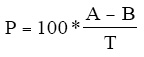
Where:
A=Measured concentration of analyte after spiking
B=Measured concentration of analyte before spiking
P=Percent recovery
T=True concentration of the spike
9.3.3 Compare the percent recovery (P) with the QC acceptance criteria in Table 2.
9.3.3.1 If P falls outside the designated range for recovery in Table 2, the CH3Hg
analysis has failed to meet the established performance criteria. If P is
unacceptable, analyze the OPR standard (Section 9.5). If the OPR is
within established performance criteria (Table 2), the analytical system is
within specification and the problem can be attributed to interference by
the sample matrix.
9.3.3.2 If the interference can be attributed to sampling, the site or discharge
should be resampled. If the interference can be attributed to a method
deficiency, the analyst must modify the method, repeat the test required in
Section 9.1.2, and repeat analysis of the sample and MS/MSD. However,
when this method was written, there were no known interferences in the
determination of CH3Hg using this method. If such a result is observed,
the analyst should investigate it thoroughly.
9.3.3.3 If the results of both the spike and the OPR test fall outside the acceptance
criteria, the analytical system is judged to be outside specified limits. The
analyst must identify and correct the problem and reanalyze the sample
batch.
9.3.4 Relative percent difference between duplicates-Compute the relative percent difference
(RPD) between the MS and MSD results according to Equation 2 using the CH3Hg
concentrations found in the MS and MSD. Do not use the recoveries calculated in Section
9.3.2.4 for this calculation because the RPD is inflated when the background concentration
is near the spike concentration.
Equation 2
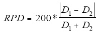
Where:
RPD=Relative percent difference
D1 =Concentration of CH3Hg in the MS sample
D1 =Concentration of CH3Hg in the MSD sample
9.3.5 The RPD for the MS/MSD pair must not exceed the acceptance criterion in Table 2. If
the criterion is not met, the system performance is unacceptable. The problem must
immediately be identified and corrected, and the analytical batch reanalyzed.
9.3.6 As part of the QC program for the laboratory, method precision and accuracy for samples
should be assessed and records maintained. After analyzing five samples in which the
recovery passes the test in Section 9.3.2, compute the average percent recovery (Pa) and
a
the standard deviation of the percent recovery (sp). Express the accuracy assessment as a
percent recovery interval from Pa - 2sp to Pa + 2sp . For example, if Pa = 90% and sp = 10%
for five analyses, the accuracy interval is expressed as 70-110%. Update the accuracy
assessment regularly (e.g., after every five to ten new accuracy measurements).
9.4 Blanks-Blanks are critical to the reliable determination of CH3Hg at low levels. The sections
below give the minimum requirements for analysis of blanks. However, it is suggested that
additional blanks be analyzed as necessary to pinpoint sources of contamination in, and external to,
the laboratory.
9.4.1 Ethylation blanks-Reagent water typically contains no CH3Hg. The reagent (ethylation)
blank may conveniently be determined by adding 0.3 mL of acetate buffer and 0.040 mL
of 1% NaBEt solution to 50 mL of reagent water in the reaction vessel.
NOTE: Do not ever use a previously ethylated water sample, as a build-up of the gas triethyl
boron will occur, which results in a negative interference and poor chromatography.
9.4.1.1 A single ethylation blank is analyzed with each analytical run, as part of
the calibration sequence. This value is used to blank correct the standard
curve.
9.4.1.2 The presence of more than 2 pg of CH3Hg indicates a problem with the
reagent water or one of the reagent solutions. An investigation of the
cause of the high blank can be made by varying, one at a time, the
amounts of buffer, reagent water, and NaBEt4 . Because NaBEt4 cannot
be purified, a new batch should be made from different reagents and
should be tested for Hg levels if the level of CH3Hg is too high. If the
reagent water is found high, this can be remedied by replacing the
purification cartridges.
9.4.2 Method blanks-The method blanks (distillation blanks) are prepared by the distillation
and analysis of 45 mL aliquots of 0.4% HCl acidified reagent water, exactly as if they
were samples.
9.4.2.1 Three method blanks should accompany each analytical batch. The mean
blank value should be less than 0.045 ng/L of CH3Hg, and the variability
should be less than 0.015 ng/L of CH3Hg. A mean blank value greater
than 0.045 ng/L CH3Hg or a variability greater than 0.015 ng/L of
CH3Hg is unacceptable for low level ambient analysis.
9.4.3 Field blanks
9.4.3.1 Analyze the field blank(s) shipped with each sample set. Analyze the
blank immediately before analyzing the samples in the batch.
9.4.3.2
If CH3Hg or any potentially interfering substance is found in the field
blank at a concentration equal to or greater than the ML (Table 1), or
greater than one-fifth the level in the associated sample, whichever is
greater, results for associated samples may be the result of contamination
and may not be reported for regulatory compliance purposes.
9.4.3.3 Alternatively, if a sufficient number of field blanks (three minimum) are
analyzed to characterize the nature of the field blanks, the average
concentration plus two standard deviations must be less than the
regulatory compliance level or less than one-half the level in the associated
sample, whichever is greater.
9.4.3.4 If contamination of the field blank(s) and associated samples is known or
suspected, the laboratory should communicate this to the sampling team so that the source of contamination can be identified and corrective
measures taken before the next sampling event.
9.4.4 Equipment blanks-Before any sampling equipment is used at a given site, the laboratory
or cleaning facility is required to generate equipment blanks to demonstrate that the
sampling equipment is free from contamination. Two types of equipment blanks are
required: bottle blanks and sampler check blanks.
9.4.4.1 Bottle blanks-After undergoing the cleaning procedures in this method,
bottles should be subjected to conditions of use to verify the effectiveness
of the cleaning procedures. A representative set of sample bottles should
be filled with reagent water acidified to 0.4% HCL and allowed to stand
for a minimum of 24 h. Ideally, the time that the bottles are allowed to
stand should be as close as possible to the actual time that the sample will
be in contact with the bottle. After standing, the water should be analyzed
for any signs of contamination. If any bottle shows signs of
contamination, the problem must be identified, the cleaning procedures
corrected or cleaning solutions changed, and all affected bottles cleaned
again.
9.4.4.2 Sampler check blanks-Sampler check blanks are generated in the
laboratory or at the equipment cleaning contractor's facility by processing
reagent water through the sampling devices using the same procedures
that are used in the field (see Sampling Method). Therefore, the "clean
hands/dirty hands" technique used during field sampling should be
followed when preparing sampler check blanks at the laboratory or
cleaning facility.
9.4.4.2.1 Sampler check blanks are generated by filling a large carboy
(Section 7.17) or other container with reagent water (Section 7.1)
and processing the reagent water through the equipment using the
same procedures that are used in the field (see Sampling Method).
For example, manual grab sampler check blanks are collected by
directly submerging a sample bottle into the water, filling the
bottle, and capping. Subsurface sampler check blanks are
collected by immersing the submersible pump or intake tubing
into the water and pumping water into a sample container.
9.4.4.2.2 The sampler check blank must be analyzed using the procedures
in this method. If CH3Hg or any potentially interfering substance
is detected in the blank, the source of contamination or
interference must be identified, and the problem corrected. The equipment must be demonstrated to be free from CH3Hg and
interferences before the equipment may be used in the field.
9.4.4.2.3 Sampler check blanks must be run on all equipment that will be
used in the field. If, for example, samples are to be collected
using both a grab sampling device and a subsurface sampling
device, a sampler check blank must be run on both pieces of
equipment.
9.5 Ongoing precision and recovery (OPR)-To demonstrate that the analysis system is within
specified limits and that acceptable precision and accuracy is being maintained within each
analytical batch, the analyst shall perform the following operations:
9.5.1 Analyze the OPR solution (0.5 ng/L, Section 7.10) followed by a ethylation blank prior to
the analysis of each analytical batch according to the procedure in Section 11. An OPR
must also be analyzed at the end of an analytical run or at the end of each 12-hour shift.
Subtract the peak height (or peak area) of the ethlyation blank from the peak height (or
area) for the OPR and compute the concentration for the blank-subtracted OPR.
9.5.2 Compare the computed OPR concentration with the limits in Table 2. If the concentration
is in the range specified, the analysis system is within specification and analysis of samples
and blanks may proceed. If, however, the concentration is not in the specified range, the
analytical process is not within the specified limits. Correct the problem and repeat the
OPR test.
9.5.3 The laboratory should add results that pass the specification in Section 9.5.2 to IPR and
previous OPR data and update QC charts to form a graphic representation of continued
laboratory performance. The laboratory should also develop a statement of laboratory
data quality for each analyte by calculating the average percent recovery (R) and the
standard deviation of the percent recovery (sr). Express the accuracy as a recovery
interval from R - 2sr to R + 2sr. For example, if R = 95% and sr = 5%, the accuracy is 85-105%.
9.6 Quality control sample (QCS)-The laboratory must obtain a QCS from a source different from
the CH3Hg used to produce the standards used routinely in this method (Sections 7.7-7.10). The
QCS should be analyzed as an independent check of instrument calibration in the middle of the
analytical batch (e.g., for a batch of 14 samples, the QCS should be analyzed after the seventh
sample). Good QCS samples may be made by KOH/methanol digestion (Reference 2) of CH3Hg
certified tissue CRMs. CH3Hg certified CRMs are available through the National Institute of
Standards Technology (NIST), National Research Council of Canada (NRCC), and International
Atomic Energy Agency (IAEA).
9.7 Depending on specific program requirements, the laboratory may be required to analyze field
duplicates and field spikes collected to assess the precision and accuracy of the sampling, sample
transportation, and storage techniques. The relative percent difference (RPD) between field
duplicates should be less than 35%. If the RPD of the field duplicates exceeds 35%, the laboratory
should communicate this to the sampling team so that the source of error can be identified and
corrective measures taken before the next sampling event.
10.0 Calibration and Standardization
10.1 Establish the operating conditions necessary to purge Hg species from the bubbler and to desorb
Hg species from the traps so that sharp peaks are given. The system is calibrated using CH3Hg
standards ultimately traceable to NIST standard total Hg reference material, as follows:
10.1.1 Calibration
10.1.1.1 The calibration must contain five or more non-zero points and the results
of analysis of one ethylation blank. The lowest calibration point must be
at the minimum level (ML).
10.1.1.2 Standards are analyzed by the addition of aliquots of the CH3Hg working
standard (Section 7.9) directly into the bubblers (Section 6.4.3). Add 50
mL of fresh reagent water, a 0.005 ng aliquot of the standard, 0.3 mL of
acetate buffer, and 0.04 mL of NaBEt4 to the bubbler, swirling to mix.
Allow to react for 17 min, and then purge and analyze as below (Section
11). Sequentially follow with aliquots of 0.05, 0.1, 0.2, and 0.01 ng
CH3Hg in separate bubblers.
10.1.1.3 For each point, correct the standard peak height or area by subtracting the
peak height or area of the ethylation blank for the analytical batch.
Calculate the calibration factor (CF) for CH3Hg for each of the five
standards using the mean ethylation-blank-corrected peak height or area
(Equation 3).
Equation 3

where:
Rs=Peak height or area of the standard
Re=Peak height or area of the ethylation blank
Cs=Concentration of the standard (ng/L)
10.1.1.4 Calculate the mean calibration factor (CFm), the standard deviation of the
CFm(SD), and the relative standard deviation (RSD) of the calibration,
m
where RSD = 100 x SD/CFm. If the RSD is # 15%, the CFm may be used
to calculate sample concentrations. If RSD > 15%, recalibrate the
analytical system and repeat the test.
10.1.1.5 The net concentration recovery (minus ethylation blank) for the lowest
standard must be in the range of 65-135% of the expected value to
continue with sample analysis.
10.2 Ongoing precision and recovery-Perform the ongoing precision and recovery test to verify
calibration prior to analysis of samples in each analytical batch. An OPR must also be analyzed at
the end of an analytical run or at the end of each 12-hour shift.
11.0 Procedure
NOTE: The following procedures for analysis of samples are provided as guidelines. Analysts
may find it necessary to optimize the procedures, such as drying time or potential applied to the
Nichrome wires, for the laboratory's specific instrumental set-up.
11.1 Sample Distillation
11.1.1 Weigh a 45-mL aliquot from a thoroughly shaken, acidified sample, into a 60-mL
fluoropolymer distillation vial. Add 200 µL of 1% APDC solution, and replace
the distillation cap, such that the tubing extends to the bottom of the vial.
11.1.1.1 Repeat this procedure for all samples to be distilled in a set, including
three reagent water blanks and spiked samples.
11.1.1.2 Matrix spikes and matrix spike duplicates-For every 10 or fewer
samples, pour two additional 45-mL aliquots from a randomly selected sample. Spike the aliquots at the level specified in Section 9.3 and process
them in the same manner as the samples. There should be two MS/MSD
pairs for each analytical batch of 20 samples.
11.1.1.3 For each sample, prepare a 60-mL distillate receiving vial. Add 5.0 mL
reagent water to each receiving vial and replace the cap so that the tubing
extends into the water layer.
11.1.1.4 Record the sample ID associated with each distillation and receiving vial.
It is important to develop an unambiguous tracking system, such as the
use of engraved vial numbers, because the distillation vials themselves
cannot be labeled (due to the heat).
11.1.2 Place each prepared distillation vial into one of the holes in the heating block and
attach the fluoropolymer tubing to the incoming gas supply from the rotometer
manifold. Adjust the gas flow rate through the bubbler to 60 ± 20 mL/min.
11.1.3 As each distillation vial with sample is placed into the heating block, place the
corresponding labeled distillation vial into the ice bath immediately adjacent to the
heating block. Attach the tubing from the receiving vessel to the port of the
distillation vessel.
11.1.4 Once all the holes in a heating block are filled, place the aluminum lid over the
vessel caps in such a way that all tubing is passing without crimps through the
slots, and the lid is making metal-to-metal contact with the block (to provide
proper heating of the lid).
11.1.5 Turn on the temperature controllers to the heating blocks to a pre-set block
temperature of 125 ± 3°C.
11.1.6 Distill the samples until each receiving vial fills to the engraved 40 mL line. This
time period will be approximately 2.5 h to 4 h depending upon exact temperatures,
gas flow rates, and water characteristics.
11.1.6.1 Different samples and locations on the block will distill at somewhat
different rates, so after about 2 h, all of the tubes should be monitored
frequently to avoid over-distillation. As the individual samples fill to the
line, they should be removed from the distillation unit.
11.1.6.2 Over-distillation is the greatest potential risk for poor recoveries by this
method. If more than the prescribed amount of sample distills over, the risk of HCl fumes co-distilling increases. Chloride and low pH are
interferences with the ethylation procedure.
11.1.6.3 If any samples are suspected of over-distillation, they should be checked
with pH paper. If the distillate has a pH of less than 3.5, it should be
discarded, rather than analyzed.
11.1.7 Once all of the vials are distilled, the distillates may be stored at room temperature
and in the dark for up to 48 h before analysis (loop the fluoropolymer tube around
to close off the second port on the receiving vial). Do not refrigerate or store
longer than 48 h.
11.1.8 The distillation-side (dirty) vials must be scrubbed thoroughly with a test-tube
brush and alkaline detergent, then rinsed in reagent water, to remove organics
prior to acid cleaning. To acid-clean between uses, the vials are filled with 10%
HCl, recapped with the tubing looped around to close off the port, and placed in
an oven at 80°C overnight.
11.2 Ethylation and purging of the distillates
11.2.1 Immediately before analysis, add 0.3 mL of acetate buffer to the sample in the
receiving vial, and then add another 10 mL of reagent water to the vial (so that the
total sample volume is > 50 mL; the vial is almost full).
11.2.2 Pour the buffered sample into the reaction vessel/bubbler, and add 0.04 mL of
freshly thawed 1% NaBEt4 solution. Close the reaction vessel with the bubbler
cap, and swirl gently to mix.
11.2.3 If standards, ethylation blanks, or QCS are being analyzed, pour 50 mL of reagent
water into the bubbler, add 0.3 mL of acetate buffer, the appropriate spike, etc.,
and 0.04 mL 1% NaBEt4 solution.
11.2.4 Allow the contents of the bubbler to react for 17 min. All CH3Hg in the sample is
converted to volatile methylethyl mercury.
11.2.5 After reaction, attach a Carbotrap® trap to each bubbler with the 1/4"
fluoropolymer fitting, and purge the sample with N2 (200 mL/min) for 17 min.
NOTE: The Carbotrap® trap must be attached such that the gas from the bubbler enters the
trap on side A.
11.2.6 Once the sample has been purged for 17 min, any adsorbed water must be dried
from the Carbotrap® trap. Disconnect the Carbotrap® trap from the bubbler and
attach the N2 flow directly to the trap. Use the same orientation (i.e., N2 entering
from side A), and purge the trap for 7 min.
11.2.7 The sample is now ready for analysis. The methylethyl mercury collected on the
trap is quantitatively stable for up to 6 h and must be analyzed within that period.
11.3 Desorption of methylethyl mercury from the Carbotrap® trap
11.3.1 Close the argon stopcock on the GC, and allow 30 sec for the pressure in the
system to dissipate. Remove the previous Carbotrap® trap from the GC.
11.3.2 Attach the Carbotrap® trap containing the new sample to the GC column using a
1/4" fluoropolymer friction fit connector, such that side A is facing toward the
GC column.
11.3.3 Place the Nichrome wire heating coil around the Carbotrap® trap, centered over,
and extending beyond the packing material on side A. Re-connect the argon gas to
side B of the Carbotrap® trap.
11.3.4 Open the argon stopcock, and allow gas to flow for 30 sec prior to heating the
column. Make sure that the post GC pyrolytic column is on and red-hot (~700°C).
11.3.5 Apply power to the coil around the sample trap for 45 sec (using an automatic
timer) to thermally desorb the ethylated species from the sample trap into the GC
column.
11.3.6 Turn on the chart recorder or other data acquisition device to start data collection.
11.3.7 Three peaks should emerge during the analytical run. The first peak (~1 min) is
Hg0, which is residual, and non-quantitative. This peak signifies the start of the
peak set. Usually, the second peak to emerge (~2.5 min) is methylethyl mercury,
the peak of interest. Following this (~4 min) is the peak for diethyl mercury
((CH3CH2)2Hg), which is the ethylation product of Hg(II). If (CH3)2Hg were
present in the sample, it would appear as a second peak between Hg0 and
methylethyl mercury-not fully resolved from the Hg0. See appendix for advice on the quantitation of (CH3)2Hg.
11.3.8 Allow the GC run to proceed at least 1 min beyond the point that the diethyl
mercury (Hg(II)) peak returns to base line. Place the next sample Carbotrap® trap
in line and proceed with analysis of the next sample.
11.4 Peaks generated using this technique should be very sharp and almost symmetrical. Methylethyl
mercury elutes at approximately 2.5 min and has a width at half-height of about 10 sec. Earlier
peaks (Hg0, (CH3)2Hg) are sharper, while later peaks (diethyl mercury) are broader.
11.4.1 The appearance of only one peak (Hg0) usually signifies either that the pyrolytic
column is not turned on, or that NaBEt4 was not added to the sample.
11.4.2 Normally the Hgo peak is quite small. However, some Hg0 is generated by thermal
degradation of diethyl mercury during the desorption step. Thus, when samples
contain a high concentration of Hg(II), both the Hg0 and the diethyl mercury peaks
will be bigger. The ratio of the two peaks is indicative of the quality of the
Carbotrap® trap. As the Carbotrap® trap degrades, the amount of thermal
breakdown of organo-mercurials increases. Since the diethyl mercury is much
more sensitive to thermal breakdown than the methylethyl mercury, monitoring the
latter peak can serve as an early warning for Carbotrap® trap replacement.
Generally, the Carbotrap® traps should be replaced any time the Hg0 peak grows
to be as large as the diethyl mercury peak. As a rule of thumb for samples with
significant Hg(II), use 1.0 ng Hg(II) from a non-acidified solution deliberately
added to the reaction vessel as a trap check. For samples very low in Hg(II), such
as blanks, the Hg0 peak is generally higher than the diethyl mercury peak, due to
residual sources.
11.4.3 In the event that samples with large Hg(II) content are analyzed, some of the
diethyl mercury generated breaks down to monoethyl mercury (CH3CH2Hg)
during thermal desorption. If this occurs, a very broad peak (width of several
minutes) will appear at some long time after the run is over (5-20 min). Such
occurrences result in a confusing and messy increase and then decrease in the
baseline. Such peaks can be hurried through the system by turning the GC column
to 140°C until the peak emerges, and then reducing the temperature back to 110°C
before resuming analysis.
12.0 Data Analysis and Calculations
12.1 Calculate the following parameters for each analytical batch:
12.1.1 Ethylation blank (n = 1) or the mean ethylation blank (n > 1)
12.1.2 Ethylation-blank subtracted calibration factor for each standard (Cfx, Section 10.1.3) and
peak measurement for each sample (Rs)
12.1.3 The mean calibration factor (Cfm), standard deviation of the calibration factor (SD), and
relative standard deviation (RSD) of the calibration factor (Section 10.1.1.4).
12.2 Compute the concentration of CH3Hg in ng/L (parts-per-trillion; ppt; Equation 4).
Equation 4
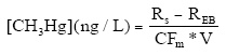
Where:
Rs=gross peak height (or area) of signal for CH3Hg in sample
Re=peak height (or area) of signal for CH3Hg in ethylation blank (n = 1) ormean ethylation blank (n > 1)
CFm =mean calibration factor
V=Sample volume (L)
12.3 The CH3Hg concentration of the mean (n=3 or more) method blank (ng/L, Equation 4) should be
subtracted from the sample concentration calculated above to obtain the net in situ CH3Hg concentration (Equation 5).
Equation 5
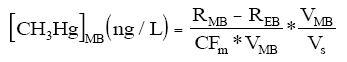
where:
RMB=gross peak height (or area) of signal for CH3Hg in the mean method blank
REB=gross peak height (or area) of signal for CH3Hg in the ethylation blank (n = 1) or the mean ethylation blank (n > 1)
CFm=Mean calibration factor
VMB=Volume of the method blank
Vs=Volume of the sample
Equation 6
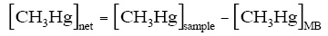
where:
[CH3Hg]net =net in situ CH3Hg concentration (ng/L)
[CH3Hg]sample=ethylation-blank corrected concentration of CH3Hg in the samplesample (ng/L, Equation 3)
[CH3Hg]MB=concentration of CH3Hg in the mean method blank (ng/L, Equation 4)
12.4 Reporting
12.4.1 All results are reported after subtraction of mean method blanks (Equation 6).
12.4.2 Under the conditions described here, the distillation procedure not 100% efficient
in recovering CH Hg because not all of the sample volume can be distilled, to
avoid co-distillation of HCl. Laboratories should calculate the efficiency of the
distillation for their laboratory. This calculation is done by keeping a running
mean of the last 30 recoveries calculated for precision and recovery samples (IPR
and OPR), excluding all values that are more than two standard deviations from
the mean. Since the distillation technique is inherently and reproducibly non-
quantitative, all results should be recovery corrected by an empirically derived
factor (Equation 7).
Equation 7

where:
F=Empirically derived correction factor
R=Recovery (the running mean of the last 30 IPR and OPR samples)
12.4.3 Report all values in ng/L to three significant figures. Report results below the ML
as <0.06 ng/L, or as required by the permitting authority or in the permit. If the
laboratory achieved an MDL lower than 0.02 ng/L (Section 1.5), a new ML may
be calculated by multiplying the laboratory-determined MDL by 3.18 and
rounding the result to the nearest multiple of 1, 2, 5, 10, etc. in accordance with
procedures described in the EPA Draft National Guidance for the Permitting,
Monitoring, and Enforcement of Water Quality-Based Effluent Limitations Set Below Analytical Detection/Quantitation Levels, March 22, 1994. Results below
this level should be reported as less than the calculated ML.
13.0 Method Performance
13.1 The method detection limit (MDL) listed in Table 1 and the quality control acceptance criteria
listed in Table 2 were validated in four laboratories. In addition, the techniques in this method have
been intercompared with other techniques for low-level CH3Hg determination in water in the
International Mercury Speciation Intercomparison Exercise (Reference 15).
14.0 Pollution Prevention
14.1 Pollution prevention encompasses any technique that reduces or eliminates the quantity or toxicity
of waste at the point of generation. Many opportunities for pollution prevention exist in laboratory
operation. EPA has established a preferred hierarchy of environmental management techniques
that places pollution prevention as the management option of first choice. Whenever feasible,
laboratory personnel should use pollution prevention techniques to address their waste generation.
When wastes cannot be feasibly reduced at the source, the Agency recommends recycling as the
next best option. The acids used in this method should be reused as practicable by purifying by
electrochemical techniques. The only other chemicals used in this method are the neat materials
used in preparing standards. These standards are used in extremely small amounts and pose little
threat to the environment when managed properly. Standards should be prepared in volumes
consistent with laboratory use to minimize the disposal of excess volumes of expired standards.
14.2 For information about pollution prevention that may be applied to laboratories and research
institutions, consult Less is Better: Laboratory Chemical Management for Waste Reduction,
available from the American Chemical Society's Department of Governmental Relations and
Science Policy, 1155 16th Street NW, Washington DC 20036, 202/872-4477.
15.0 Waste Management
15.1 The laboratory is responsible for complying with all federal, state, and local regulations governing
waste management, particularly hazardous waste identification rules and land disposal restrictions,
and for protecting the air, water, and land by minimizing and controlling all releases from fume
hoods and bench operations. Compliance with all sewage discharge permits and regulations is also
required.
15.2 Acids, samples at pH <2, and BrCl solutions must be neutralized before being disposed of, or must
be handled as hazardous waste.
15.3 For further information on waste management, consult The Waste Management Manual for
Laboratory Personnel and Less is Better: Laboratory Chemical Management for Waste
Reduction, both available from the American Chemical Society's Department of Government
Relations and Science Policy, 1155 16th Street NW, Washington, DC 20036.
16.0 References
16.1 Frontier Geosciences, Inc., Purchase Order 97-1-003 from DynCorp Viar, Inc., January, 1997.
16.2 Bloom, N.S "Determination of Picogram Levels of Methylmercury by Aqueous Phase Ethylation,
Followed by Cryogenic Gas Chromatography with Cold Vapor Atomic Fluorescence Detection."
Can. J. Fish Aq. Sci. 1989, 46: 1131.
16.3 Bloom, N.S and Fitzgerald, W.F. "Determination of Volatile Mercury Species at the Picogram
Level by Low Temperature Gas Chromatography With Cold Vapor Atomic Fluorescence
Detection." Anal. Chim. Acta. 1988, 208: 151.
16.4 Horvat, M., Bloom, N.S., and Liang, L. "A Comparison of Distillation with other Current Isolation
Methods for the Determination of Methyl Mercury Compounds in Low Level Environmental
Samples Part 2, Water" Anal. Chim. Acta, 1993, 282: 153.
16.5 Bloom, N.S. and von der Geest, E.J. "Matrix Modification to Improve Recovery of CH3Hg from
Clear Waters using the Acid/Chloride Distillation Procedure," Wat Air Soil Pollut 1995, 80: 1319.
16.6 Liang, L., Horvat, M., and Bloom, N.S. 1994. "An Improved Speciation Method for Mercury by
GC/CVAFS After Aqueous Phase Ethylation and Room Temperature Precollection," Talanta 1994, 41: 371.
16.7 Bloom, N.S., Coleman, J.A., and Barber, L. "Artifact Formation of Methyl Mercury During
Extraction of Environmental Samples by Distillation." Fres. Anal. Chem. 1997, (in press).
16.8 Method 1669, "Method for Sampling Ambient Water for Determination of Metals at EPA Ambient
Criteria Levels," U.S. Environmental Protection Agency, Office of Water, Office of Science and
Technology, Engineering and Analysis Division (4303), 401 M Street SW, Washington, DC
20460, April 1995 with January 1996 revisions.
16.9"Working with Carcinogens," Department of Health, Education, and Welfare, Public Health
Service. Centers for Disease Control. NIOSH Publication 77-206, Aug. 1977, NTIS PB-277256.
16.10 "OSHA Safety and Health Standards, General Industry," OSHA 2206, 29 CFR 1910.
16.11 "Safety in Academic Chemistry Laboratories," ACS Committee on Chemical Safety, 1979.
16.12 "Standard Methods for the Examination of Water and Wastewater," 18th ed. and later revisions,
American Public Health Association, 1015 15th Street NW, Washington, DC 20005. 1-35:
Section 1090 (Safety), 1992.
16.13 Bloom, N.S. "Trace Metals & Ultra-Clean Sample Handling," Environ. Lab. 1995, 7, 20.
16.14 "Handbook of Analytical Quality Control in Water and Wastewater Laboratories," U.S.
Environmental Protection Agency. Environmental Monitoring Systems Laboratory, Cincinnati, OH
45268, EPA-600/4-79-019, March 1979.
16.15 Bloom, N.S.; Horvat, M.; Watras, C.J. "Results of the International Mercury Speciation
Intercomparison Exercise," Wat. Air. Soil Pollut., 1995, 80, 1257.
17.0 Tables and Diagrams
Table 1
Methyl Mercury Analysis Using Method 1630: Lowest Water Quality Criterion, Method
Detection Limit, and Minimum Level
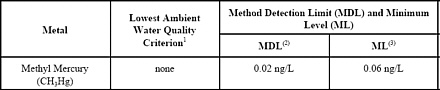
NOTES:
1.
Lowest of the freshwater, marine, and human health ambient water quality criteria
promulgated by EPA for 9 States and the District of Columbia at 40 CFR Part 131
on May 4, 1995 (60 FR 22229)
2.
Method Detection Limit as determined by the procedure in 40 CFR Part 136,
Appendix B.
3.
Minimum Level (ML)
Table 2
Quality Control Acceptance Criteria for Performance Tests In EPA Method 1630
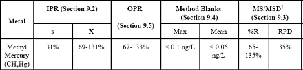
NOTES:
1.
Recovery corrected
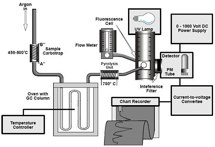
Figure 1
Schematic Diagram of the Cold Vapor Atomic Fluorescence Spectrometer (CVAFS)
Detector interfaced with the isothermal GC and pyrolytic decomposition column.
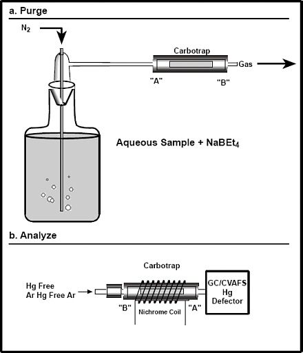
Figure 2
Schematic Diagram of Bubbler Setup (a), and Carbotrap® trap orientation (b).
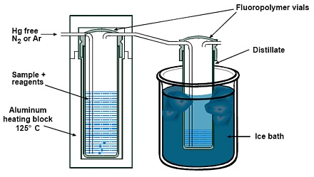
Figure 3
Schematic diagram showing the CH3Hg distillation set-up.
18.0 Glossary
The definitions and purposes below are specific to this method, but have been conformed to common usage
as much as possible.
18.1 Ambient Water: Waters in the natural environment (e.g., rivers, lakes, streams, and other receiving
waters), as opposed to effluent discharges.
18.2 Analytical Batch: A batch of up to 20 samples that are oxidized with the same batch of reagents
and analyzed during the same 12-hour shift. Each analytical batch must also include an OPR and
a QCS. MS/MSD samples must be prepared at a frequency of 10% per analytical batch (one
MS/MSD for every 10 samples).
18.3 Intercomparison Study: An exercise in which samples are prepared and split by a reference
laboratory, then analyzed by one or more testing laboratories and the reference laboratory. The
intercomparison, with a reputable laboratory as the reference laboratory, serves as the best test of
the precision and accuracy of the analyses at natural environmental levels.
18.4 Matrix Spike (MS) and Matrix Spike Duplicate (MSD): Aliquots of an environmental sample to
which known quantities of the analyte(s) of interest is added in the laboratory. The MS and MSD
are analyzed exactly like a sample. Their purpose is to quantify the bias and precision caused by
the sample matrix. The background concentration(s) of the analyte(s) in the sample matrix must be
determined in a separate aliquot and the measured values in the MS and MSD corrected for these
background concentrations.
18.5 May: This action, activity, or procedural step is allowed but not required.
18.6 May not: This action, activity, or procedural step is prohibited.
18.7 Minimum Level (ML): The lowest level at which the entire analytical system must give a
recognizable signal and acceptable calibration point for the analyte. It is equivalent to the
concentration of the lowest calibration standard, assuming that all method-specified sample
weights, volumes, and cleanup procedures have been employed. The ML is calculated by
multiplying the MDL by 3.18 and rounding the result to the number nearest to (1, 2, or 5) x 10n,
where n is an integer.
18.8 Must: This action, activity, or procedural step is required.
18.9 Quality Control Sample (QCS): A sample containing CH3Hg at known concentrations. The QCS
is obtained from a source external to the laboratory, or is prepared from a source of standards
different from the source of calibration standards. It is used as an independent check of instrument
calibration.
18.10 Reagent Water: Prepared from 18 M ohm ultrapure deionized water starting from a prepurified
source. Reagent water is used to wash bottles, as source water for trip and field blanks, and in the
preparation of standards and reagents.
18.11 Sample set: Samples collected from the same site or, if for compliance monitoring, from a given
discharge. This term applies to samples collected at the same time, to a maximum of ten samples.
18.12 Shall: This action, activity, or procedure is required.
18.13 Should: This action, activity, or procedure is suggested, but not required.
18.14 Stock Solution: A solution containing an analyte that is prepared from a reference material
traceable to EPA, NIST, or a source that will attest to the purity and authenticity of the reference
material.
18.15 Ultraclean Handling: A series of established procedures designed to ensure that samples are not
contaminated for CH3Hg during sample collection, storage, or analysis.
Appendix A
Determination of Dimethyl Mercury
1.0 Scope and Application
1.1 This method is for determination of dimethyl mercury ((CH3)2Hg) in unfiltered water by direct purge and trap, isothermal GC separation, and CVAFS detection.
1.2 The method described in this appendix is not supportable by the full range of QC samples, so the
method is to be considered for research purposes only.
1.3 The method described in this appendix is subsidiary to Method 1630 (Methyl Mercury in Aqueous
Samples by Aqueous Phase Ethylation, Purge and Trap, and CVAFS). As such, only the major
differences between the (CH3)2Hg method and the CH3Hg method will be described.
1.4 This method is designed for the determination of in the range of 0.0002 to 0.1 ng/L, and may be
extended to higher levels by selection of a smaller sample size.
1.5 Since no reagents are added to the sample, the MDL is not ethylation blank limited, but is only
limited by the instrumental noise. With the Tekran analyzer, the MDL for a 1 L sample volume is
approximately 0.0002 ng/L as Hg (based on 7 replicates of a 0.0015 ng/L solution).
2.0 Summary of Method Changes
2.1 The analysis is performed using fresh, unfiltered, unpreserved samples. To minimize analyte
losses, all efforts must be extended to speed the time between sample collection and sample
analysis, and to minimize the contact of the sample with the atmosphere prior to purging.
2.2 Samples should be purged and analyzed in the field, but if this is not possible, samples may be
collected directly into headspace-free 1-L glass bottles with fluoropolymer-lined caps, and sent via
express to the laboratory for analysis. If kept unpreserved, dark, and cool, the (CH3)2Hg present in
3 2
the sample is found to be stable for up to 48 h from the time of collection.
2.3 Under no circumstances can plastic bottles of any kind (including fluoropolymer) be used for the
collection of samples for the determination of (CH3)2Hg. The half-life of dissolved (CH3)2Hg in
fluoropolymer bottles is only about 6 h.
2.4 The entire 1 L sample is purged directly onto a Carbotrap® trap, using N2at a flow rate of 300
mL/min for 30 min. A specially constructed 1 L bottle with 24/40 ground glass fitting and frittedbubbler cap must be utilized for this purpose. After purging, the trap must be dried with N2 and
analyzed within 6 h, as described in method 1630.
2.5 The analyzer set-up for (CH3)2Hg is exactly as in Method 1630, with the exception that the GC
oven must be set at 80°C rather than 110°C, to facilitate separation of Hg0 from (CH3)2Hg.
2.6 Upon desorption of the Carbotrap® trap into the GC column, up to two peaks will appear. The
first is usually Hg0, which appears at approximately 1.0 min. The second is (CH3)2Hg, which
appears approximately at 1.5 min.
NOTE: Because these peaks are so close to each other, and either one or the other, or neither
may be present, it is imperative that an event marker be triggered to signal the start of the GC
run, so that the peak may be positively identified by its retention time.
2.7 Calibration is performed by spiking appropriate aliquots of a (CH3)2Hg standard into the same
volume of reagent water as the samples, and purging onto Carbotrap® traps. A good calibration
range is from 1 to 100 pg as Hg.
2.8 The stock solution for (CH3)2Hg is a 1.0 parts per million solution in methanol, custom prepared
by Strem Chemical (Newburyport, MA). A working stock (1 ng/mL) is prepared by 1:1000
dilution of the stock solution with methanol. These solutions have been found to be stable for over
4 years, when kept refrigerated, and dark, in glass bottles.
2.9 The stock solution as supplied by Strem is only approximate in its concentration. To exactly
calibrate the solution, an aliquot of the working stock equal to approximately 1 ng is spiked into a
bubbler of pre-purged reagent water, and then purged onto a gold coated sand trap. The trap is
analyzed for total Hg according to EPA Method 1631. In this case, total Hg purged onto the trap
equals (CH3)2Hg. Pre-calibrated working standards of (CH3)2Hg in methanol are available for
purchase (Frontier Geosciences Inc., or equivalent).
3.0 QC Measures
3.1 Not all QC measures available for method 1630 are available for use with the (CH3)2Hg technique.
3.1.1 For each set of samples (or batch of 20), three method blanks, and two MS/MSD pairs
should be measured. Since (CH3)2Hg is rarely detected in the environment, matrix spikes
should be low (i.e., 1-5 pg), to assure the ability to measure near the MDL.
3.1.2 No certified reference materials (CRMs) or second source LCSWs are available for
(CH3)2Hg.
3.2 No interferences have been observed for this method, although volatile organic compounds, as
might be present in waste waters and effluents could diminish the observed (CH3)2Hg signal by co-
eluting, and quenching the atomic fluorescence.
3.3 Separate field samples should be collected for replicates, and matrix spikes, since once the sample
is opened, (CH3)2Hg will rapidly be lost from solution by diffusion to the air.
3.4 Samples must not be filtered prior to analysis, or (CH3)2Hg will be lost to the air.
3.5 Samples must not be stored acidified, or (CH3)2Hg will decompose to CH3Hg. Samples may be
acidified just prior to analysis, if Hg0 and (CH3)2Hg are to be both purged simultaneously (as in
Method 1631 Appendix).
3.6 Samples should be kept out of light, or (CH3)2Hg will decompose to CH3Hg.
3.7 Samples must not be stored in plastic containers, or (CH3)2Hg will rapidly be lost by diffusion into
the plastic matrix.
4.0 Performance
4.1 This method is not often used, and so has not been rigorously tested. However, experience
indicates that the following QC objectives can be met in ambient water samples, when using 1 L
samples.
5.0 Tables
Table 1
Dimethyl Mercury Analysis Using Method 1630 Appendix: Lowest Water Quality
Criterion, Method Detection Limit, and Minimum Level
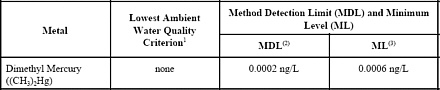
NOTES:
1.
Lowest of the freshwater, marine, and human health ambient water quality criteria promulgated by
EPA for nine States and the District of Colubia at 40 CFR Part 136 on May 4, 1995 (60 FR 22229).
2.
Method Detection Limit as determined by the procedure in 40 CFR Part 136, Appendix B.
3.
Minimum Levels (ML).
Table 2
Quality Control Acceptance Criteria for Performance Tests In EPA Method 1630
Appendix
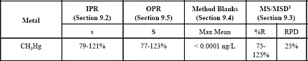
NOTES:
1.
Recovery corrected.
|